
At the heart of the machine tool is a precision spindle used to apply the required torque, speed, and level of accuracy necessary to perform a specific machining application. Although there are hundreds of parts in most spindles, a typical spindle assembly consists of the rotating shaft, driven by an internal or external motor, and supported by a bearing system that’s been properly located within a housing. The shaft has multiple functions and acts as a housing for the drawbar mechanism, which ultimately holds the tool in place while the spindle is under load. Below is a brief description on each of the components and subsystems.
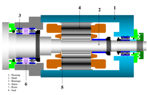
Whether belt-driven, gear-driven, or an integral motor design, every spindle’s drive system is determined by the speed, power, and stiffness required in the application. Belt and gear-driven spindles are typically used when the process requires greater torque and are powered by an external motor and pulley system. A combination of gear sets and pulley ratios are used to increase or decrease torque as needed. Integral motor designs, normally used in higher speed applications, provide torque and power through a system where the stator (a stationary component of an electric induction motor that produces a magnetic field) and rotor (rotational component of an electric induction motor) are located within the spindle housing itself.
The spindle housing could be an integral part of the machine, a block style, or a flange-mounted cartridge, among other designs. It provides multiple utility systems to the spindle, such as lubrication channels for the bearings, drilled air passages for positive internal pressure, and cooling jackets to reduce heat. The critical function of the housing, however, is to accurately support the bearing arrangement on the shaft and dampen vibration levels emanating from the machining process.
Depending on the speed, torque, and load requirements, the type of bearing used plays a significant factor in the life of a spindle. For high-speed units, angular contact ball bearings are the standard choice. However, for applications requiring greater stiffness and load capacity, roller bearings provide a higher contact angle and are often the more appropriate option. Lubrication methods, precision levels, preload amount, and overall configuration are determined in accordance with the demands and conditions of the application.
With external contamination being the leading cause of premature spindle failure, seals are required to prevent swarf and other contaminants from entering the bearings. The two primary types of seals are contact and non-contact. Contact seals are the simplest form, consisting of a lip that sits directly on the surface of the shaft. Lip seals are subject to the rotational forces of the shaft, however, and will inevitably wear down throughout the life of the spindle.
Non-contact seals, by contrast, are designed with fixed and rotational parts pieced together. Passageways between these mating components provide a labyrinth to deter direct access to the bearings. In combination with positive internal air pressure, a non-contact labyrinth seal allows for adequate protection against contamination while minimizing heat and wear due to zero surface-to-surface contact. The type of seal used in any design is ultimately determined by the criteria of the application, complexity of the spindle and space available within the housing.
The main purpose of the shaft is to transmit torque from the drive system. It is held in place with a series of bearings that allow it to rotate along the centerline of the spindle. A typical spindle shaft is often hollow and tapered at one end to incorporate a tool retention system or drawbar.
The drawbar mechanism rides within the shaft and consists of a rod outfitted with a spring stack to provide the necessary force for clamping and unclamping the tool. The force stems from an actuating cylinder on the back of the drawbar that functions via hydraulic or pneumatic pressure. The front of the drawbar is equipped with a gripper used to clamp the tool and hold it in place while under load.
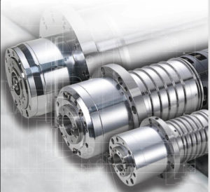
Spindles are complex, highly engineered components that are critical to every machine tool. They come in various shapes and sizes and are engineered to accommodate countless machining needs. As the industry leader in precision spindle design, manufacturing, and rebuild services, SETCO is here to help. Please get in touch with us today for more information on standard or custom spindle designs.